Installation of the High Temperature Heater or Heater/Cooler Element
The thermoelectric Heater/Cooler element transfers heat from one side of the element to the other side. Thus it requires good thermal conduction between the Heater/Cooler element and the cooling water in the reservoir. Two options are available to ensure adequate thermal conduction:
- Thermally conductive, electrically insulating pads (reorder Bruker part number 499-000-261)
- Wakefield Engineering Thermal Compound, from Wakefield Engineering (part number 120-2)
Wakefield Engineering Thermal Compound is required to reach temperatures below –20°C but is messier than thermal pads, which are therefore preferred when possible.
NOTE: The shelf life of the thermal pads is 1 year.
CAUTION: The heater /cooler element is extremely delicate.
- Always handle it with care; do not drop it.
- The top of the element is particularly delicate. Do not set it on a table with the top side facing down.
- When not in use, keep it in its protective foam box.
- Clean the element gently with a cotton swab and isopropyl alcohol.
Procedure:
- If you are using the Heater/Cooler Element, place a thermally conductive, electrically insulating pad or spread thermal compound on the base of the Heater/Cooler element. If you are using thermal compound on the base of the heater, also spread some thermal compound onto the mating surface of the scanner.
CAUTION: Use the thermally conductive pads only on the Heater/Cooler element; do not use them with the High Temperature Heater element.
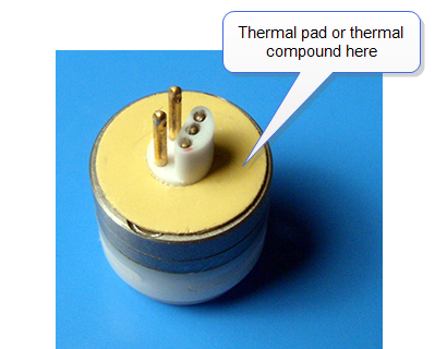
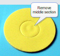
Figure 1: Thermally Conductive, Electrically Insulating Pad Mounted on Heater/Cooler Element
NOTE: Remove the center section to place the pad on the Heater/Cooler element:
- Insert the Heater/Cooler or High Temperature Heater element into the connector on the top of the scanner as shown in Figure 2.
CAUTION: The heating element must be plugged in and unplugged in a straight orientation (no side-to-side motion). Failing to do so can cause damage to the piezo crystal.
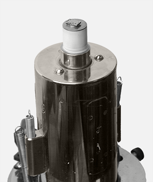
Figure 2: Heater/Cooler Element (with Sample Puck and Sample) Installed on the Scanner
NOTE: You may place the sample puck and sample on the heating element as shown in
Figure 5 or wait until step 5. If you are using the Heater/Cooler element, spread a small amount of thermal compound under the sample puck.
- Place the silicone seal around the heating element and scanner piezo guard. Press down on the seal until it rests against the top of the scanner body (see Figure 3).
- If necessary to facilitate installation, lubricate the silicone seal and piezo guard with the provided silicone grease.
Figure 3: Placement of the Silicone Seal Around the Heater, Mounted on the Scanner
- Install the spacer block:
- Slide the spacer block straight down and around the silicone seal.
CAUTION: Do not hit the heater/cooler element. It is fragile.
NOTE: Initial setup may require the use of the silicone lubricant provided.
- Verify that the fit between the seal and the block is tight. The spacer block should be centered and level.
- Verify that the grooves on the bottom of the spacer block align with the positioning balls on the top of the scanner and that the spacer block is sitting flat.
Figure 4: Addition of a Spacer Block (a), Head (b), and Probe Holder (c) to the Scanner
- Place the sample puck (with the sample pre-mounted) on top and centered on the heating element if you haven't done so already:
Figure 5: Positioning of a Sample Puck
NOTE: If you are using the Heater/Cooler element, spread a small amount of thermal compound under the sample puck.
- Position the Dimension Icon head on the spacer block and secure the head to the scanner with the four springs (see Figure 4, b and c).
- Use the Tip Up switch on the Dimension Icon base to move the head and spacer block upward with respect to the sample. This will help to avoid damage to the sample when inserting the probe holder.
- Insert a spare Luer fitting (to be used as a handle) into one of the three openings on the front face of the probe holder (see Figure 6, a). Fully raise the probe holder clamp inside the head to get it out of the way for probe holder placement.
- Install a probe in the probe holder if you haven’t already.
- Holding the probe holder by its Luer handle, tilt it up while approaching the head (see Figure 4, c).
- Insert the probe holder into the head so the outer edge of the metal ring on the base of the probe holder presses against the inside of the silicone seal (see Figure 6, a). Using blunt tweezers (to avoid puncturing the silicone seal), gently lift the silicone seal around the metal ring while lowering the probe holder onto the silicone seal (see Figure 6, b).
Figure 6: Placement of the Probe Holder Metal Ring Inside the Silicone Seal
NOTE: Because the probe holder is transparent, you can verify that the seal encloses the entire metal ring and touches the body of the probe holder all the way around the ring.
- Tighten the middle knob on the back of the head to lower the clamp on to the probe holder to secure it in place.
- Align the laser beam to reflect into the photodetector from the tip-end of the cantilever.
The system is now ready for use.
CAUTION: The surface of the heating element can be hot. Touching could result in burns on contact.
| www.bruker.com
|
Bruker Corporation |
| www.brukerafmprobes.com
|
112 Robin Hill Rd. |
| nanoscaleworld.bruker-axs.com/nanoscaleworld/
|
Santa Barbara, CA 93117 |
| |
|
| |
Customer Support: (800) 873-9750 |
| |
Copyright 2010, 2011. All Rights Reserved. |
Open topic with navigation